Linuxslate.com Builder's Guide:
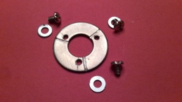
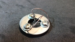
I call it the WW3SSII Device (Washer With 3 Screws Stuck In It).
So what does a WW3SSII Device do? It helps you take over the world....
OK well, it probably won't really help you do that,at least not directly,
but it will help you make Cloverleaf Antennas that are closer to commercially built ones.
|
April 2014
Updates:
|
Discuss
this Guide on the Linuxslate.com Forums  |
(What is presented here is derivative work of Alex (IBCrazy). It is based on this article on RC Groups.)
Cloverleaf antennas are a circularly polarized omni-directional antenna commonly used for FPV (First Person View) piloting of RC(Radio Controlled) Aircraft (Also called Video Piloting). Cloverleaf antennas significantly out-perform linearly polarized antennas in cases where the relative orientation of the transmitting antenna and the receiving antenna is changing, and when used at frequencies where multi-pathing becomes problematic. Both of these conditions exist with modern FPV flying. While references to similar circular polarized, omni directional antennas where described in Ham Radio and Communications publications many years ago, their recent resurgence and use in FPV applications is credited to Alex (IBCrazy). Alex provided a DIY (Do It Yourself) tutorial on the aforementioned RC Groups article.
I originally made several cloverleaf antennas based on Alex's original instructions. While testing proved the antennas out-performed whip antennas, I found it impossible for me to make professional-looking cloverleafs. I needed a way to help me make better cloverleaf antennas.
In an effort to improve symmetry, I attempted to make them using 3 separate lobes instead of the 2 and 1 method Alex originally described. This did produce an antenna that was more symmetrical, but it was very difficult to hold the 3 lobes while soldering. If I attempted to reheat them, the whole thing would fall apart. I needed some sort of jig or holder. I had several ideas - a "helping hands" like device with several extra arms - Too awkward and expensive. A wood jig - Would take too long to make. Then I realized that all I needed was a flat surface that would clamp the bottom (horizontal) part of each lobe. I had my solution - It would be cheap, and quick enough to build for my impatience.
The device as described is for making 5.8GHz antennas, but 2.4 or 1.3 GHz antennas can be made with the same device.
The device described is for 3 lobed cloverleafs. Obviously, one can be made for making 4 lobed Skew Planar Wheels (WW4SSII).
Disclaimers:
This article describes building antennas that can be connected to either a transmitter or a receiver. While a faulty antenna cannot damage a receiver, it can permanently damage your video transmitter. The type of antenna described here was not designed by the author of this document. The author is not attesting to the suitably of such an antenna for any application, or its suitability for use with any particular transmitter. Responsibility for the construction and use of described antennas is solely the responsibility of the reader/builder.
Certain operations described here involve potential hazards, and require the use of proper workshop practice and personal protective equipment (PPE). Readers not familiar with proper workshop practices, and thus the type and use of PPE, must learn those things prior to attempting to perform the work described here.
This describes a method for those who have already decided to take on the challenge and receive the satisfaction of making their own antennas. I am not suggesting or advocating making your own antennas in leu of purchasing genuine IBCrazy commercially produced products.
I do, however recommend one of those 2 options over purchasing antennas of unknown pedigree. See above about possible transmitter damage. If you buy a poor quality cloverleaf or "mushroom antenna", you will loose your money, and you may loose a transmitter, or possibly a whole aircraft. You will gain nothing. "Learning" that a certain vendor ripped you off is not really learning. If you build the WW3SSII, and use it to make your own antenna,
even if the worst happens, and you loose a transmitter or aircraft, at least you have gained skill and experience.
(Why plain steel? - Copper or Aluminum are too good a conductor of heat. Despite the wire (lobe) being clamped into the WW3SSII, soldering the antenna is no problem when steel is used. Also, softer materials will not hold the threads as well. Harder materials are simply more difficult to drill and thread)
We must now mark a line every 120 degrees. This can be done with a protractor, but I simply placed the washer on a printed diagram of a circle with 120 degree lines. It can also be done by drawing equal lateral triangles. It doesn't matter how you do it, so long as you can mark the washer every 120 degrees.
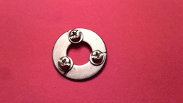
Next, center punch the washer on each line, and approximately 6 - 7mm from the center point of the circle (The one pictured is my first prototype, and the screws are slightly too far out for optimal use building a 5.8GHz antenna, but it works). Where this is on the washer will depend on the washer you use. It needs to be near the center of the horizontal part of a 5.8GHz antenna. Even if you build larger antennas, make the jig for 5.8GHz.
Drill holes the proper size for the tap you will use. I used 6 - 32 screws, so that is a number 32 drill. Do not clean out the hole. We need all the material we can get to hold the threads. A finer thread will mean more threads in a given thickness of material.
Using the correct tap, thread the holes. Once the holes are threaded, you can remove any sharp bits with a file.
We now need to make the channels for the wire to sit in. They are tangent to the holes, and should be straight from the inside to the outside. You don't really need to re-measure. As long as the screw holes are pretty close to 120 degrees, and you keep the channels on the proper side of each screw, they should remain pretty close to 120 degrees.
 Using a Rotary tool with
a thin cut-off wheel, make the slots. I use 0.030in welding wire to
make my 5.8GHz cloverleafs, so the channels should be about 0.010in deep.
Using a Rotary tool with
a thin cut-off wheel, make the slots. I use 0.030in welding wire to
make my 5.8GHz cloverleafs, so the channels should be about 0.010in deep.
Install the washers and screws. I used what I believe are PC Hard drive mounting screws. Optionally, peen the ends of the screws or purposely damage (bugger) the last couple threads so that the screws won't fall out.
(Optional - apply Teflon tape (as used in plumbing) to the screw threads. This holds the loose screws in the threads, and allows them to be lightly tightened while positioning the lobes.)
The reader is encouraged to read the first several posts of the referenced RC Groups thread to become familiar with cloverleaf antennas and their construction before proceeding.
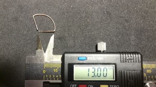
Obtain some 0.025 - 0.035in dia. solid welding wire. (You will also need a length of appropriate coax cable, or a coax assembly as shown in the RC Groups thread.) Do not use flux core welding wire. As per the instructions in the RC Groups thread, cut 3 of the short wires only. We will not make the long wire. For 5.8GHz, the wire is 53 mm long. Bend each wire 13 mm from each end to form a long, square "U". Next, work along the center span, bending it into a uniform curve until the ends of the wire meet. They will not/should not make a 90 degree angle. Work/rework the curve until it is smooth and uniform, and the lobe can lay flat.
Make 2 more identical lobes.
Insert the horizontal wire of a lobe under one of the washers.

Lightly tighten the screw so that the lobe can be both pivoted,and moved latterly. With the WW3SSII oriented so that the lobe is toward your right (as shown), angle that lobe away from you at a 45 degree angle (for RHCP). In other words, the plane of the lobe should be approximately perpendicular to a line pointing at your face. You can use a 45 degree wedge cut from paper or other material, or you can achieve good enough results just by "eye-balling" it.
Rotate the WW3SSII clockwise 120 degrees (viewed from above), insert the next lobe, and align in a similar manner. Repeat for the third lobe.
Do a final alignment of all 3 lobes. Loosen or tighten the screws as needed to allow for alignment. Without disturbing the adjacent lobe, tighten each screw enough to hold the lobe. There are not a lot of threads there. Do not tighten so much that you damage the them.
Carefully examine the alignment and tweek as necessary.
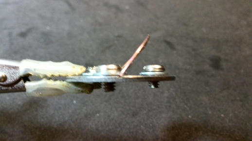
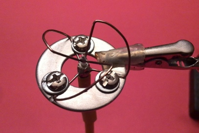 Put the WW3SSII assembly in a small hobby vise or
helping hands, and solder the lower (ground) lobe ends.
Put the WW3SSII assembly in a small hobby vise or
helping hands, and solder the lower (ground) lobe ends.
Gently bend (not pivot) the lobes as needed so that the upper ends meet about 2 mm above the lower intersection. The leads should just touch without being under stress. If you think you might have stressed the lower solder joint, re-flow it.
Insert the coax cable from the bottom, mark it so that the top connection will connect to the center conductor and the bottom connects to the shield. Remove the coax, and carefully strip it. Re-insert, and solder the lower antenna point to the shield. If nothing was under stress, and the screws were tight enough, nothing should move when you re-heat it to solder the coax.
 (Optional - At this point, with the
bottom (shield) soldered, and the center conductor not touching anything, you
can do an optional check. Use a MultiMeter in continuity or
resistance mode to test between the shield and center conductor.
At this point you should *not* have continuity. If you do,
either the coax assembly was bad, (i.e. connector was installed
improperly), or you overheated the coax while soldering the
shield.)
(Optional - At this point, with the
bottom (shield) soldered, and the center conductor not touching anything, you
can do an optional check. Use a MultiMeter in continuity or
resistance mode to test between the shield and center conductor.
At this point you should *not* have continuity. If you do,
either the coax assembly was bad, (i.e. connector was installed
improperly), or you overheated the coax while soldering the
shield.)If there is not continuity, solder the top antenna connection to the center coax conductor. Again, thanks to the WW3SSII, you should be able to do this without anything moving.
Make sure you do not solder bridge the top and bottom. The distance between the top and bottom connections is important. You do not want them to touch (obviously). You also do not want them so close that they form a tiny capacitor. At 5.8GHz even a very tiny capacitance means a significant impedance. Similarly, too much distance distorts the antenna, and changes it's tuning. Keep the distance about 1 - 2mm. The one shown has a copper ground plane or balun, and the gap between the top connection, and the bottom is larger than it would be ideally.
Let it cool, and remove it from the WW3SSII device.
Cover the connection areas with hot glue, silicone or epoxy. Do not use epoxy that contains metallic substances.
Always do a ground range test before flying.
(Note: The WW3SSII can also be used to re-from or repair a crash (or otherwise) damaged cloverleaf antenna. Remove any glue/covering as needed. Lower the antenna into the WW3SSII with the lobes between the screws. Loosen the screws, and rotate the antenna so that the lobes go into the slots. If the lower part of a lobe is bent or detached, leave that screw loose. Tighten the screw of each good lobe. Clamp the WW3SSII, and reshape the antenna as needed using 2 needle nose pliers. While care must still be used so that none of the good solder connections are stressed or torqued, the WW3SSII device will help maintain alignment, and prevent further damage. Resolder as needed.)
Please discuss this article on the Linuxslate.com Forums.
Back to Contents
Links:
Linuxslate.com Forums for this device
| Disclaimer: THIS DOCUMENT IS PROVIDED BY THE AUTHOR "AS IS". IN NO EVENT SHALL THE AUTHOR BE LIABLE FOR ANY DIRECT, INDIRECT, INCIDENTAL, SPECIAL, EXEMPLARY, OR CONSEQUENTIAL DAMAGES ARISING IN ANY WAY OUT OF THE USE OF THIS DOCUMENT, EVEN IF ADVISED OF THE POSSIBILITY OF SUCH DAMAGE. |
All trademarks/tradenames and images are the property of the companies that own them.
Images copyright (c) 2014 linuxslate.com